
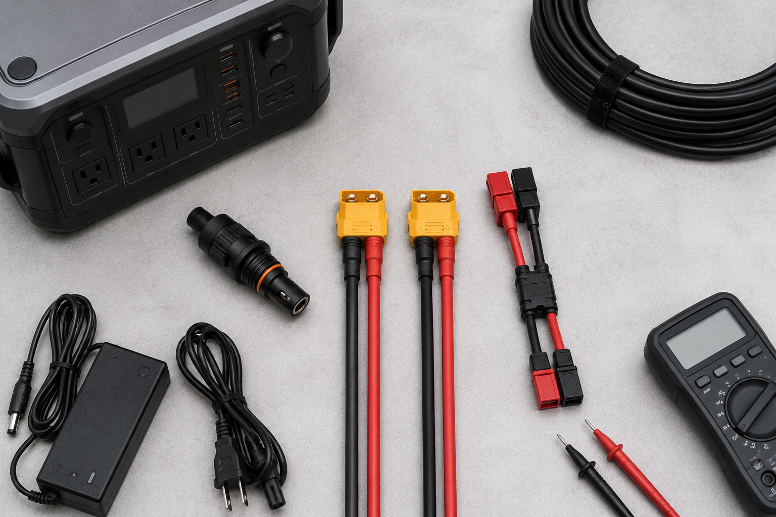
This portable power station hardware guide explains how cables, connectors, polarity, cable gauge, and solar adapters affect safety, compatibility, and charging performance.
The quality of any portable energy system is fundamentally limited by the components that connect the solar array to the power station. In off-grid setups, solar adapters are not just accessories. They are the bridge between photovoltaic generation and the battery management system.
Using poor-quality connectors, thin-gauge wiring, or incorrectly wired adapters can reduce charging efficiency, create unnecessary heat, and increase the risk of damaging a portable power station’s DC input system.
This article explains the principles used to evaluate portable power station cables, connectors, adapters, polarity, and cable construction. The Hardware Vault is the site’s directory for browsing hardware categories and related specialist guides.
The Technical Standard for Solar Adapters in Portable Power Stations
When selecting solar adapters, the most important technical factor is the complete relationship between current, resistance, cable length, and connector quality — not wattage alone. Cable conductor size becomes more important as circuit current and total cable length increase. Panel wattage alone does not determine the correct cable gauge, because the same wattage can involve different current levels at different voltages.
A connector that fits is not enough on its own — cable construction, expected current, total circuit length, and the documented ratings of every connector and adapter in the path all matter. Detailed cable-gauge and voltage-drop guidance appears later in this guide, in Cable Gauge and Thermal Efficiency.
For a wider explanation of charging efficiency, panel placement, and input behaviour, read the Solar Charging Optimisation Guide.
Connector Integrity: MC4, XT60i, and DC Inputs
MC4 connectors remain among the most common standards for portable and rigid solar panels because they provide secure, weather-resistant connections. However, many failures occur at the adapter point, where MC4 cables connect to a power station’s proprietary input.
For EcoFlow users, the XT60i connector is especially important because it includes a signalling pin that a standard XT60 connector lacks — without it, some EcoFlow models may limit charging current to around 8A. See the visual connector identification guide to tell MC4, XT60, XT60i, and DC barrel connectors apart, and the MC4-to-XT60 and MC4-to-XT60i adapter selection guide for full detail — a connector that mechanically fits does not by itself prove voltage, current, polarity, pinout, or functional compatibility.
For a full troubleshooting walkthrough, read our EcoFlow solar charging stuck at 8A guide.
For Jackery users, compatibility depends on the model and input type. Some units use DC7909, DC8020, or 8mm-style inputs, while others may require specific adapter types. Before connecting third-party solar panels, the voltage range, connector size, polarity, and current rating should always be checked.
Polarity Standards: EcoFlow vs. Jackery
Polarity management is a critical safety step when working with solar adapters. Barrel-style connectors often use a centre-positive configuration, but this is not universal — some older power stations, third-party panels, or adapter kits use a different layout. Barrel connector size and polarity must be verified for the exact equipment involved; see the DC barrel connector size and polarity guide for the full comparison.
Before making the first connection, it is good practice to verify polarity with a multimeter — see the dedicated polarity-checking guide for the full, safe step-by-step method. A reversed polarity connection can prevent charging, trigger protection systems, or, in worse cases, damage the DC input board of the power station.
Cable Gauge and Thermal Efficiency
Not all solar adapters are built for the same current load. A thin cable used with a high-wattage solar array can create resistance, heat, and voltage loss. This can cause the power station to receive less power than expected, even when the solar panels are performing correctly.
AWG (American Wire Gauge) describes conductor size, but a gauge number alone does not independently prove that a cable is safe for a given setup. Appropriate conductor size depends on the complete circuit: expected current, total circuit length, conductor material, cable resistance, insulation and temperature rating, installation environment, connector and adapter ratings, acceptable voltage drop, and the exact equipment manufacturer’s documentation.
10AWG may be useful in some higher-current or longer-run solar setups. 12AWG may be appropriate in other, smaller or shorter documented configurations. Neither gauge is universally correct — the right choice depends on the current, length, and ratings of the specific setup being built. A thicker conductor also does not compensate for incorrect voltage, reversed polarity, an unsuitable connector, an under-rated adapter, a damaged termination, or an unknown pinout.
Voltage-Drop Estimate (Symbolic Method)
Voltage drop is the reduction in voltage along the complete cable circuit because the conductor and its connections have resistance. The calculation must use the full round-trip conductor path — the length of cable current travels out AND back — not just the one-way distance.
R_total ≈ 2 × L × r
V_drop ≈ I × R_total
Voltage drop (%) ≈ (V_drop ÷ V_system) × 100
L = one-way cable length. r = conductor resistance per unit length, for the actual material, gauge, and stated temperature. I = expected circuit current. V_system = the voltage used for the comparison.
Use resistance data from the actual cable manufacturer or a reliable conductor specification — copper and copper-clad aluminium are not interchangeable in this calculation, and resistance changes with temperature. Connector, crimp, splice, and adapter losses are additional to this simplified cable-only estimate.
This formula is an engineering estimate, not a laboratory measurement of your exact cable. A lower-voltage system experiences a larger percentage voltage drop from the same absolute voltage-drop value than a higher-voltage system does. The equipment manufacturer’s own requirements remain controlling — always check the official manual or specification for your exact power station and panel before relying on any estimate.
Environmental Resistance and Build Quality
Solar adapters are often used outdoors, exposed to sunlight, dust, moisture, and repeated movement. Good adapters should use durable insulation, secure connector housings, and well-moulded terminals to reduce the risk of arcing, corrosion, or loose contact.
For outdoor use, weather-resistant connectors and UV-resistant cable insulation are important. Materials such as XLPE insulation are often preferred because they handle heat and sunlight better than basic cable jackets.
Portable Power Station Hardware Selection Checklist
Before connecting solar hardware to a portable power station, confirm the following:
- Exact power station manufacturer, model, and input type.
- Connector family (MC4, XT60, XT60i, DC barrel, or other) on both the panel side and the station side.
- Polarity, verified for the exact equipment rather than assumed from appearance.
- Cable conductor material, gauge, and total circuit length.
- Voltage, current, and wattage ratings for every cable, connector, and adapter in the path.
- Environmental and temperature rating if the setup is used outdoors.
- Whether the official manual or manufacturer documentation confirms the setup.
For the complete electrical compatibility calculations — including array Voc, Vmp, Imp, and Isc — see the Portable Power Station Compatibility Checklist.
Do Not Connect the Hardware If
Stop and do not connect the setup if any of the following are true:
- The connector family, pinout, or polarity has not been confirmed for the exact equipment.
- The cable, connector, or adapter current and voltage ratings are unknown or unclear.
- The cable gauge, length, or voltage-drop estimate has not been checked against the expected current.
- The official manual or manufacturer documentation does not confirm the setup.
- Any connector, cable, or termination shows visible damage, corrosion, or looseness.
Final Hardware Compatibility Verdict
Once the checklist above has been completed, classify the setup using one of the following four outcomes:
- Compatible as documented — connector family, pinout, polarity, voltage, current, and cable ratings are all confirmed and correctly matched against the manufacturer’s own documentation.
- Conditional — voltage, current, and polarity are confirmed safe, but wattage, cable gauge, length, or environmental factors still need attention before or during use.
- Electrically or mechanically incompatible — a confirmed voltage, current, polarity, or connector mismatch exists. Do not connect.
- Insufficient information — one or more required specifications is unknown or undocumented. Do not connect until it is confirmed.
How This Guide Is Sourced
This guide is based on established electrical and photovoltaic principles for connector families, cable construction, polarity, and voltage drop.
The voltage-drop method above was verified against an independent engineering reference (EngineeringToolbox.com’s treatment of Ohm’s law and round-trip conductor resistance) — it is a general estimation method, not a measurement of any specific reader’s cable.
The author has not physically tested every cable, connector, adapter, or power station discussed in this guide, and this guide is not manufacturer approval for any specific setup.
Always verify your exact equipment’s specifications against its official manufacturer manual or documentation before connecting solar hardware to a portable power station.