
Publication history: Originally published 17 May 2026. Substantially reviewed and updated 23 August 2026.
Purpose: answer one bounded question: Can this documented solar panel or array be connected to this documented portable power station without exceeding the manufacturer’s published input limits?
This is a documentation-and-calculation method. It is not a physical product test, a manufacturer approval, or a guarantee of safety. A result is only as reliable as the exact model, regional variant, port, panel datasheet and temperature assumptions entered.
If your portable power station is not charging or showing 0W input, you must check solar panel compatibility before replacing cables, adapters, or panels.
The T9 Ten-Gate Compatibility Method
Do not start with wattage or connector shape. Pass the gates in order. A failure at a hard limit ends the assessment.
Gate 1 — Identify the exact station and solar-input port
Record the manufacturer, full model name, region, manual revision and specific PV/DC input. Find the manufacturer’s operating or MPPT voltage range, absolute maximum input voltage, maximum input current, maximum accepted solar power, connector requirements and array restrictions.
Manufacturer examples: EcoFlow documents the DELTA 2 solar input as 11–60 V DC, 15 A maximum and 500 W maximum, and instructs users to keep panel output voltage within 60 V. BLUETTI documents the AC180P as 12–60 V DC, 10 A and 500 W maximum. Those numbers belong to those exact models; they are not universal.
Gate 2 — Build the panel/array input sheet
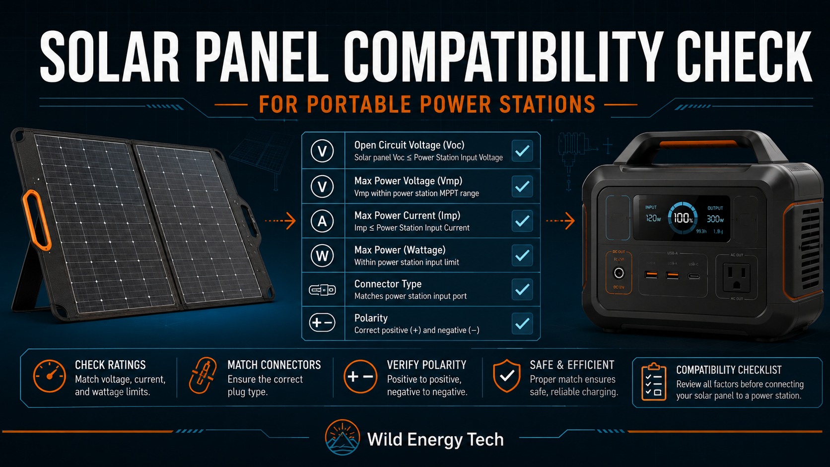
From the panel label or manufacturer datasheet, record rated power (Pmax), open-circuit voltage (Voc), maximum-power voltage (Vmp), short-circuit current (Isc), maximum-power current (Imp), the Voc temperature coefficient, connector and polarity. Do not substitute a marketed “12 V” or “24 V” class for actual Voc or Vmp.
| Value | Meaning | Compatibility use |
|---|---|---|
| Voc | Voltage with no load | Hard maximum-voltage and cold-weather check |
| Vmp | Voltage near maximum power | Operating/MPPT-range check |
| Isc | Short-circuit current | Controller, protection, cable and connector check |
| Imp | Current near maximum power | Expected operating-current check |
| Pmax | Rated STC power | Power-limit and clipping check |
| βVoc | Voc temperature coefficient | Cold-weather voltage estimate |
Gate 3 — Calculate array voltage and current
For NS matched panels in each series string and NP matched strings in parallel:
- Vocarray,STC = Vocpanel × NS
- Vmparray ≈ Vmppanel × NS
- Imparray ≈ Imppanel × NP
- Iscarray ≈ Iscpanel × NP
- Parray,STC = Ppanel × NS × NP
These are planning equations for matched modules under comparable conditions. Mismatch, shading, temperature and controller behaviour can reduce usable output. They do not relax a manufacturer limit.
Gate 4 — Estimate cold-weather Voc
Use the panel’s own Voc temperature coefficient. If βVoc is expressed as a decimal per °C:
Voccold = VocSTC × [1 + βVoc × (Tminimum cell − 25°C)]
For a complete series string:
Vocarray,cold = Vocpanel × NS × [1 + βVoc × (Tminimum cell − 25°C)]
A nominal coefficient of −0.25%/°C is entered as −0.0025/°C. If the datasheet states ±0.03%/°C, the cold-voltage conservative end is −0.28%/°C because the more-negative coefficient produces the larger cold Voc. Use that conservative end for a hard-limit conclusion when tolerance could change the result. A cold temperature produces a negative temperature difference, so multiplying two negative values increases estimated Voc. Use a defensible minimum cell temperature; ambient temperature is only a proxy. If the coefficient or minimum temperature is missing, classify the result as insufficient evidence instead of guessing.
Victron’s MPPT installation guidance explicitly instructs designers to consider both array Voc and its temperature coefficient when sizing series strings.
Gate 5 — Apply the hard maximum-voltage rule
Compare calculated cold array Voc with the station’s documented absolute maximum input voltage. If array Voc can exceed that limit, the outcome is DO NOT CONNECT. A current limiter, wattage limit, BMS or matching connector does not make over-voltage acceptable.
Gate 6 — Check the operating/MPPT voltage range
Compare array Vmp with the station’s documented operating range. Voc can be below the maximum while Vmp remains too low for reliable startup or tracking. Use the exact station documentation; the bottom of a broad input range does not necessarily have the same controller meaning on every model.
Gate 7 — Check operating and short-circuit current
Compare calculated Imp and Isc with every applicable station, port, cable, branch connector, fuse and adapter limit. Some controllers limit what they draw, but manufacturer rules differ. A published “15 A max” is not blanket permission for an arbitrarily large parallel array.
Gate 8 — Evaluate rated array power and over-paneling
Compare array Pmax with maximum accepted solar power. Excess nameplate wattage may be unused or clipped only where manufacturer/controller documentation permits it. Never infer permission from voltage compliance alone. The Over-Paneling analysis separates documented clipping from unsupported configurations.
Gate 9 — Verify the complete physical path
Confirm panel connector, adapter, station connector, pinout, voltage/current ratings, cable conductor and environmental rating. XT60 and XT60i can mechanically mate while producing different behaviour on some EcoFlow equipment. Similar DC barrel connectors can differ in inner-pin diameter.
Gate 10 — Verify polarity
Confirm manufacturer markings and documentation, or verify solar panel polarity with a multimeter using a safe procedure. Connector shell appearance is not proof of polarity. If polarity is unknown, stop.
Outcome Classification
| Result | Meaning |
|---|---|
| COMPATIBLE BASED ON DOCUMENTED LIMITS | Calculations and physical checks are inside documented limits. This is not an absolute safety guarantee. |
| COMPATIBLE WITH LIMITATIONS | The documented configuration is allowed, but input may be limited, clipped or conditional. |
| NEEDS ADAPTER OR CONFIGURATION CHANGE | Electrical limits may work, but the present wiring, connector, polarity or series/parallel arrangement does not. |
| NOT ENOUGH EVIDENCE — CHECK MANUFACTURER | A coefficient, limit, port rule or manufacturer permission is missing or ambiguous. |
| DO NOT CONNECT | A hard limit is exceeded or polarity/connection safety cannot be established. |
Worked Cases From Published Specifications
Evidence base: The EcoFlow DELTA 2 manual publishes limits of 11–60 V, 15 A and 500 W. The NextGen 220 W panel manual lists Voc 21.5 V, Vmp 18.4 V, Isc 12.4 A, Imp 11.9 A and βVoc −(0.25±0.03)%/°C. The arithmetic below is calculated by T9 from those published figures; no physical testing is claimed.
Case A — One panel: compatible based on electrical limits
- At −10°C using the nominal −0.25%/°C coefficient: factor = 1 + (−0.0025 × −35) = 1.0875.
- Cold Voc = 21.5 × 1.0875 = 23.38 V.
- Vmp = 18.4 V; Imp = 11.9 A; Pmax = 220 W.
Using the conservative tolerance end, −0.28%/°C, gives 21.5 × 1.098 = 23.61 V; the conclusion is unchanged. The values sit inside the cited DELTA 2 limits. Result: COMPATIBLE BASED ON DOCUMENTED ELECTRICAL LIMITS, subject to correct cable, connector, polarity, actual coefficient and current manual.
Case B — Three panels in series: do not connect
STC array Voc = 21.5 × 3 = 64.5 V. It exceeds the DELTA 2’s 60 V maximum before cold adjustment. Result: DO NOT CONNECT.
Case C — Two panels in series: inside the cited limits
- Nominal cold Voc at −10°C = 21.5 × 2 × 1.0875 = 46.76 V; using the conservative −0.28%/°C tolerance end gives 47.21 V.
- Array Vmp ≈ 36.8 V.
- Array Imp ≈ 11.9 A.
- Array Pmax = 440 W.
All values sit inside the cited DELTA 2 figures. Result: COMPATIBLE BASED ON DOCUMENTED ELECTRICAL LIMITS, with the same physical-connection limitations.
Case D — Two panels in parallel: current evidence is insufficient
- Cold Voc remains approximately 23.38 V.
- Vmp remains approximately 18.4 V.
- Imp ≈ 23.8 A.
- Isc ≈ 24.8 A.
- Pmax = 440 W.
Voltage and wattage fit, but calculated panel current exceeds the published 15 A maximum. The cited manual does not grant blanket permission for any higher-current array. Result: NOT ENOUGH EVIDENCE — CHECK ECOFLOW. Possible controller limiting is not manufacturer approval.
Case E — Cold weather can reverse a warm-weather decision
Consider a documented panel with Voc 55 V and βVoc −0.30%/°C against a 60 V station maximum. At 25°C, 55 V appears below the limit. At −10°C:
55 × [1 + (−0.0030 × −35)] = 60.78 V.
The cold estimate exceeds 60 V. Result: DO NOT CONNECT at that minimum-temperature condition. This is a transparent hypothetical calculation illustrating the method, not a named-product test.
Compatibility Record Sheet
| Record | Your value | Evidence |
|---|---|---|
| Station model, region, manual revision, input | _____ | Manufacturer manual/support |
| Operating/MPPT voltage range | _____ V | Manufacturer manual |
| Absolute maximum voltage | _____ V | Manufacturer manual |
| Maximum current / Isc rule | _____ A | Manufacturer manual/support |
| Maximum accepted solar power | _____ W | Manufacturer manual |
| Panel Voc / Vmp / Isc / Imp / Pmax | _____ | Panel label/datasheet |
| βVoc and minimum cell temperature | _____ | Datasheet/site assumption |
| NS / NP | _____ / _____ | Array design |
| Calculated cold array Voc | _____ V | T9 formula |
| Connector, cable rating and polarity | _____ | Documentation/verified measurement |
| Classification and unresolved limits | _____ | Ten-gate decision |
Stop Conditions
- Calculated cold array Voc can exceed the absolute maximum.
- Array Vmp does not meet documented operating/start requirements.
- Current or protection requirements are exceeded or absent.
- The manufacturer does not document the proposed over-paneling arrangement.
- Connector pinout, cable rating or polarity is unknown.
- Specifications come only from an unverified retailer listing.
- The exact model, region, port or panel datasheet cannot be confirmed.
Evidence Used and Scope
- EcoFlow DELTA 2 User Manual — station voltage, current, wattage and voltage warning.
- EcoFlow NextGen 220 W Panel Manual — Voc, Vmp, Isc, Imp, power and temperature coefficients.
- BLUETTI AC180P official specifications — contrasting model input limits.
- Victron MPPT installation guidance — maximum Voc and temperature-coefficient sizing.
- Victron MPPT sizing calculator — independent calculation cross-check.
For deeper explanation use Voc vs Vmp, Series vs Parallel, and Over-Paneling. Those modules explain individual decisions; this page remains the controlling T9 methodology.